|
|||||
|
Tinkering |
QL Keys, part 1IntroductionAnnounced in 1982 and introduced in 1984, the Sinclair QL was intended as a compact office computer. It featured 128 KiB of RAM, a Motorola 68008 CPU and built-in mass storage (the unusual "microdrives"), all of which made it - at least on paper - a serious alternative for its contemporaries.
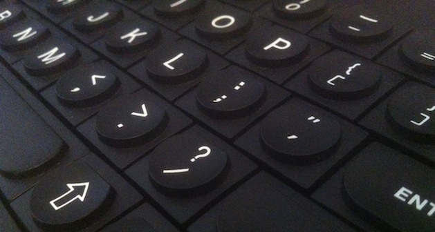
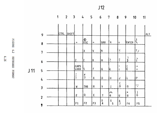
The QL case was designed by Rick Dickinson, who had been been involved with the Sinclair Spectrum and a host of other Sinclair products before the QL. When confronted with the QL in real life, either in the eighties or now, one is readily struck by its cool good looks. If a dilophosaurus - who must have known nothing about computers or industrial design - were alive today, I have no doubt at all that it would quickly state that "The Sinclair QL is the best-looking computer ever made, m'kay?" Despite that sentiment, the machine does seem somewhat dated in the performance area. And how exactly do I start a web browser? Plus, I can't find how to switch the graphics to True Color mode. Considerations like these would normally spell doom for a piece of office equipment, but in this particular case (check it, a pun!) it would be a shame to let a pleasing design be discarded, just because the hardware won't let you play mp3's on it. I have therefore endeavored to relieve a QL with defective ROMs that had come into my possession of its nearly 30 years-old interior to see how far I can take it to the present. There's plenty of space inside once the main board with the microdrives is removed, and the keyboard shows promise as well - a relatively standard lay-out (compare that to a first-gen Spectrum!) with function keys, shift, control, and alt modifier keys, and a backslash. Warning: no warranty is offered for the following. Proceed at your own risk! Adapting the keyboard to USBThe QL keyboard is a prominent feature of the case, and to make it work as an input device for present-day computing it must be made to speak USB. Some interface work is needed for such a thing, both in electronics and in software. The former is done using a modern microcontroller and the Sinclair QL Service Manual, which happily contains a diagram of the keyboard matrix. For the software I had much benefit of an open source library that provides USB connectivity for microcontrollers and which I found to have been used for projects similar to this one, involving retro-hacking the C64 and the BBC micro.
HardwareOn the QL main board, the keyboard is decoded by an "Intel 8049 Intelligent Peripheral Controller" or IPC; the alphanumeric keys are arranged in an 8x8 sub-matrix, and the shift, control and alt modifier keys are placed in individual separate columns. The whole is cleverly wired in such a way that only 8 outputs and 8 inputs are required on the IPC, despite the fact that the entire matrix consists of 9 rows x 11 columns.
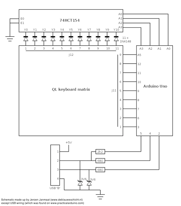
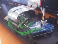
After removing the logic board, the function of the 8049 is to be taken over by an Arduino Uno device. A choice made for reasons of convenience; Arduinos are cheap, easy to program and I had one lying around anyway. The basic version has 14 digital I/O lines and 6 analog inputs, which in fact can be reprogrammed to act as digital I/O lines as well, giving a total of 20 digital inputs or outputs. I decided not to try to emulate Sinclair's 8x8 wiring, but to do a scan of all 9 rows and 11 columns. In order to fit those and the 3 lines used for the envisaged USB port on the 20 available I/O lines, it was necessary to extend that number somehow; in this case by using a 74HCT154 decoder. This TTL-compatible component uses four input lines to select one of sixteen outputs; "selection" means that that particular output is made 0V (or active low) while the others remain 5V (or "high"), behavior similar to the 8049 implementation. The scheme is used to scan 11 keyboard matrix columns using just 4 Arduino digital output lines. The diagram below shows how the scanning logic is implemented.
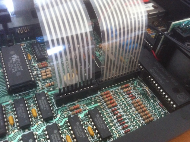
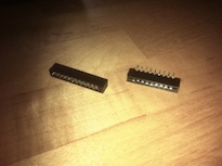
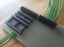
Note the diodes, added to prevent shorts between the 74HCT154 outputs when certain combinations of keys are pressed at the same time. It should also be mentioned that the ATMEGA328p microcontroller on the Arduino will have its built-in pull-up resistors enabled on the 9 input lines, obviating external resistor arrays. The USB port seen in the lower part of the schematic will carry the connection with the host (the standard USB port on the Arduino Uno cannot be used for that). Wires A0 to A3 on the Arduino are configured as digital outputs and cycle through binary numbers from 0000 to 1010 in order to scan the columns through J12. Digital inputs 3, 6 through 12 and A5 are used to determine the state of each row on J11. The realisation of this circuit requires some means to connect the very thin leads of the QL keyboard membrane to the rest of the circuit. For this case I simply desoldered the connectors from the original main board, as it was kaput anyway (not sure if these connectors are easily to be had elsewhere). Below are some pictures showing the 9 and 11 pin connectors after desoldering, and the experimenting board on which they are placed together with sockets for the 74HTC154 plus diodes.
When in use, the Arduino is powered by the +5V provided by the USB port of the host machine that it is connected to via the +5V pin on the Arduino. On the Arduino website it is mentioned that powering an Arduino directly through the I/O pins (as opposed to the power plug or the USB connector) is not recommended on account of the absence of fuses on that side to protect the electronics from over-voltage. Nevertheless this is how the circuit is wired; I do not foresee a situation where the 5V supply voltage would be exceeded here in any situation approaching normal use. SoftwareThe software needed for the conversion consists of two parts; a routine for the scanning and decoding of the keyboard and a part that sends the appropriate character - taking into account pressed modifier keys (control, shift and alt) - to the USB port. The scanning routine determines the state of every key by setting columns "low" in turn and then scanning the states of the lines. A flag is set if a key is pressed, with some bookkeeping of modifier keys. A look-up table then provides the corresponding key, along with some extra trickery in order to generate the backspace key, "control-alt-delete", extra function keys, et cetera. To send data over USB I made use of the vusb-for-arduino library found here (version 005). It's pretty straightforward to install; unzip the archive and copy the directory named "UsbKeyboard" to the "libraries" folder in the Arduino IDE. There's some example code included which is perfectly easy to adapt. I found that the character list in "UsbKeyboard.h" needed to be expanded to feature extra keys that seemed necessary; to learn more about that, look through the USB HID specification. Apart from some small matters the source code is complete and functional. That is to say, with the electronics put together and the microcontroller programmed, the QL keyboard can be attached to a Mac, PC or Linux computer via USB, and it will be recognized as a human interface device and usable as a keyboard. One software issue still to be addressed is a working "alt-tab" implementation to cycle through running applications, but meanwhile version 1.0 is available for download for your hacking pleasure. QL Keys sketch for Arduino Credits/useful URLs
(Originally written 2012/07/02)
|
