|
||||||||||||||
|
Tinkering |
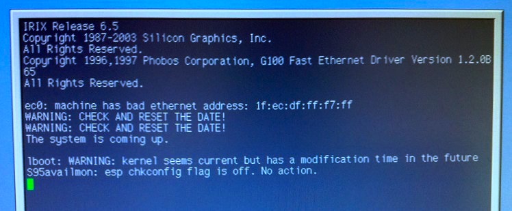
Revitalizing an Silicon Graphics Indy timekeeper chip(Note: The technical part of this page owes much to this discussion (Note: dead link; the Nekochan site is defunct as of 2018). The approach described below however is specifically written for the Dallas timekeeper chip used in the Silicon Graphics Indy.) IntroductionThe Silicon Graphics Indy was intended as a low-cost Unix workstation, and was produced and sold in the mid-nineties of the last century. An active hobbyist community has shown that old does not mean obsolete; software is still being ported and developed for the IRIX operating system - albeit mostly for the MIPS4 platform - and a large part of that will run on the Indy. Although the machine is certainly solidly built in the pizza-box style (one can place a 21-inch CRT on top of it), there are one or two issues that an owner will have to deal with sooner or later. The issue addressed on this page concerns the "Dallas" real-time clock. This component is a chip on the main board; it keeps track of time when the machine is turned off and holds the hardware network address. To enable it to do its job when mains power is disconnected from the machine, it has an internal battery. That is, a 3 volt battery is integrated in the casing of the Dallas chip. But batteries go flat after a while, and this one is no exception. After ten years of service, the Indy will start to show signs of forgetfulness; at boot time it will remark that its ethernet address is bad and that the date should be checked. Another symptom is that the lively start-up tune is no longer played.
The normal remedy for this ailment would be to replace the Dallas chip, but new chips of this type are becoming increasingly difficult to find and they may be expensive. Another way to solve the problem is to extract the empty battery from the chip and put a new battery back in. What follows is a illustrated sequence of steps that I took to do just this. Locating and extracting the Dallas chip
First remove the power lead from the machine. Once the cover (or "skin" in SGI speak) is slid off the chassis, the Dallas chip can be found; it is located on the lower right corner of the main board, close to the disk brackets. A rather fat IC package marked "Dallas" with the code "DS1386-8k-150" printed underneath. In my case, it also had a picture of a dog's head on it (suspiciously looking like Spike from the Tom & Jerry cartoons). To remove the chip, gently rock it back and forth (not side to side) and it will come free after a while. Note that the device has a "dot" on one corner to indicate where pin number one is. It should be put back in the same orientation. The legs are prone to bending, so be careful there. While working on the device with a file, saw, or dremel, it would be a good idea to mount it on an unused IC socket in order to avoid bending the pins. A small vise or similar tool also helps to stabilize the chip while working on it, further reducing risk of damaging the legs. Exposing the battery
The next step is to locate the battery. I found it by using a magnet; it turned out to lie beneath the "dog face". How to unearth it is up to the operator and the tools he has available. I used a small hacksaw that is intended for metal work and was aided by the fact that the outline of the battery could actually be discerned on the surface of the chip - there was a slight "bulge" indicating the contours. Eventually I removed enough of the surrounding material to expose the battery. The photos above show that there is a lead attached to the top of the battery. This is its negative pole and it can be gently pried off with a knife. The affair seems a bit fragile and a part of the lead may break off; it's important to keep enough of the latter accessible to be able to solder a wire to it. Once sufficient material has been removed to expose the sides of the battery, it can be carefully forced up from the casing (using a small screwdriver for example). Another lead similar to the one found before is attached to the bottom or positive side; be careful so as not to break it. That wire must be pried off as well. Beneath the battery and a further layer of resin is part of the integrated electronics and should remain intact. Attaching a new battery
The old battery turns out to be a BR1632 that is specified to supply 3 volts. Drawing from examples elsewhere (see note at the beginning), I used the ubiquitous CR2032 type (also 3 volts) and an appropriate holder as a replacement. To each lead a short piece of wire was soldered and attached to the holder. Note the polarity! The holder is glued to the unopened side of the Dallas chip and the new battery inserted. Reconfiguring the Indy
Finally the Dallas chip can be put back in its socket on the Indy main board (in the correct orientation!). Straighten the legs on the chip first if necessary. Re-attach the power lead and peripherals and turn the machine on. Press the escape key when the "maintenance" option appears on the boot screen and press 5 to enter the command monitor. Here, the date command can be used to set the current (GMT) time and date. The hardware ethernet address should be adjusted as well; use the setenv command: setenv -f eaddr nn:nn:nn:nn:nn:nn, where nn:nn:nn:nn:nn:nn is a unique hexadecimal number. This number should be found on a label on the back of the Indy chassis. After leaving the command monitor, the machine can be rebooted and is once again ready for use. Credits/useful URLs
(Originally written 2013/06/05)
|